Product Design
Why Are My Injection Molded Parts Failing?
By Dr. Duane Priddy Sr. · Published September 15, 2022
FORENSIC EVIDENCE
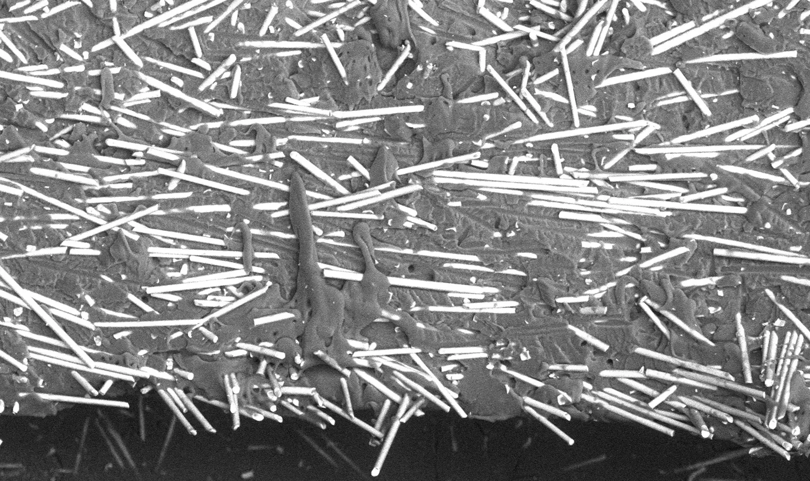
Pictured: Scanning electron micrograph of a knit line fracture surface, with bright glass fibres lying parallel to the fracture rather than bridging across it
A CASE STUDY
The following case study is the property of Plastic Expert Group and cannot be copied or distributed without prior permission. Our case analysis does not imply that this specific plastic failure will happen systematically. Every case is unique and should be treated accordingly.
PROBLEM: WHY ARE MY INJECTION MOLDED PARTS FAILING?
Most failures of injection molded plastic parts are caused by either improper design of the part or improper design of the mold. Most failures occur at what are called “weld lines” or “knit lines”.
As the melted plastic fills the mold, there are locations where the molten plastic flow stream separates and then comes back together. When two plastic melt flows come together, the knitting of the polymer chains is not always complete causing a point of weakness in the part.
This is especially true if the plastic is reinforced by the addition of glass fibers. The fibers must bridge across the knit line. If the fibers end up parallel to each other and do not bridge across the knit line, the knit line is exceptionally weak as shown in Image 1.
Image 1: SEM of a knit line fracture showing most of the glass fibers are parallel with the fracture
SOLUTION: COMPUTER MODELING
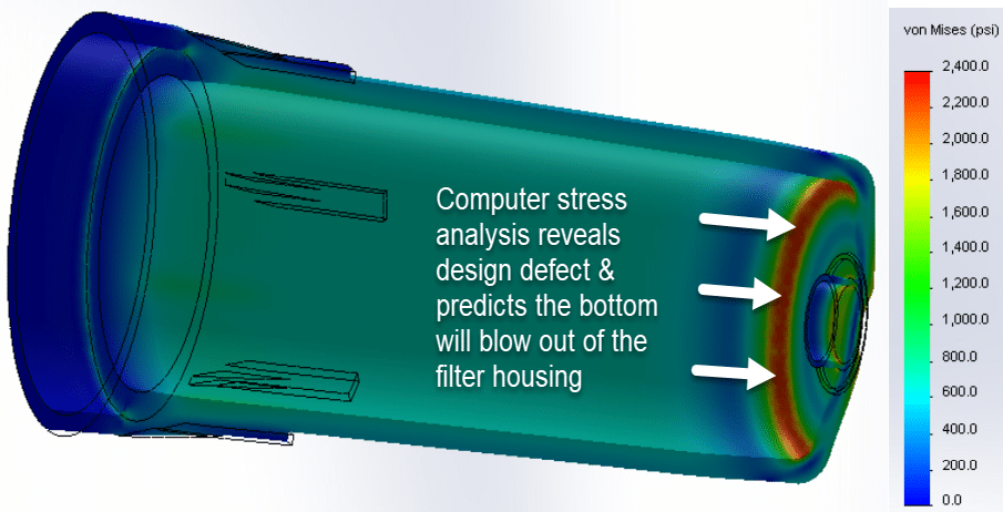
In order for injection molded parts to be reliable and not fail during their intended service, two types of computer modeling should be done including Finite Element Analysis (FEA) and Mold Fill & Pack Analysis (MF&P).
FEA is used to design the part and MF&P is used to design the mold. Proper location and sizing of the mold gate is critical, especially if the plastic contains glass fibers. Image 2 shows an example of how the mold design was optimized taking the knit lines into consideration.
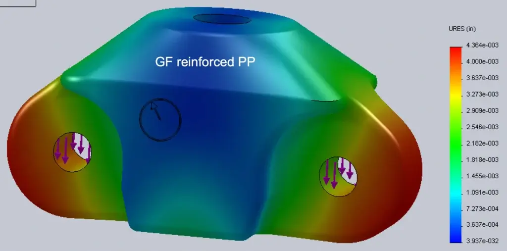
Image 2: Design mold with gates placed so knit lines are not located in the red areas
Plastic Expert Group are experts in plastic failure analysis, plastic part design, Finite Element Analysis, and Mold Fill & Pack Analysis. We are equipped to perform not only static FEA, but we also have high speed computers that can perform dynamic FEA simulations which will predict fatigue failure of plastic part designs.
Feel free to share your problem or questions with us and let’s discuss!
Plastic failure intelligence, monthly
Forensic case studies, failure-mode explainers, and plastics standards updates from our polymer scientists.
About one email a month. Unsubscribe anytime.
Related articles

Discuss your matter with a polymer scientist
Our experts provide independent technical opinion on plastic and polymer failures.